
Combination of Plain/Geared trolley with Traversing Rails
Combination of Plain / Geared trolley with Traversing Rails
Trolley model
Max. working load ( ton )
( number of falls )
| 0.25 ・ 0.5
| 1S ・ 1W
| 1.5 ・ 2S ・ 2W
| 2.5 ・ 3W
| |||||
Min. I-beam Width ( c )
| 32
| 31
| 47
| 67
| |||||
I-beam
H X B X t1/t2 (mm)
| Ix (cm4)
| ( a )
| ( b )
| ( a )
| ( b )
| ( a )
| ( b )
| ( a )
| ( b )
|
600x190x16/35
| 130000
| ||||||||
600x190x13/25
| 98400
| ||||||||
450x175x13/26
| 48800
| 300
| 3
| 300
| 3
| ||||
450x175x11/20
| 39200
| 312
| 9
| 312
| 9
| ||||
400x150x12.5/25
| 31700
| 252
| 4
| 252
| 4
| ||||
400x150x10/18
| 24100
| 294
| 2
| 266
| 11
| 266
| 11
| ||
350x150x12/24
| 22400
| 204
| 5
| 204
| 5
| ||||
350x150x9/15
| 15200
| 250
| 5
| 240
| 3
| 222
| 14
| 222
| 14
|
300x150x11.5/22
| 14700
| 158
| 7
| 158
| 7
| ||||
300x150x10/18.5
| 12700
| 193
| 2
| 165
| 10
| 164
| 10
| ||
300x150x8/13
| 9480
| 204
| 7
| 194
| 5
| 176
| 16
| 176
| 16
|
250x125x10/19
| 7310
| 114
| 10
| 114
| 10
| ||||
250x125x7.5/12.5
| 5180
| 155
| 8
| 145
| 6
| 127
| 16
| 127
| 16
|
200x150x9/16
| 4460
| 98
| 4
| 88
| 2
| 70
| 13
| 70
| 13
|
200x100x7/10
| 2170
| 110
| 10
| 100
| 8
| 82
| 19
| 82
| 19
|
180x100x6/10
| 1670
| 90
| 10
| 80
| 8
| ||||
150x125x8.5/14
| 1760
| 52
| 6
| 42
| 4
| ||||
150x75x5.5/9.5
| 819
| 61
| 11
| 51
| 9
| ||||
125x75x5.5/9.5
| 538
| 36
| 11
| ||||||
100x75x5/8
| 281
| ||||||||
Trolley model
Max. working load ( ton )
( number of falls )
| 5
| 7.5
| 10
| ||||
Min. I-beam Width ( c )
| 48
| 73
| 73
| ||||
I-beam
H X B X t1/t2 (mm)
| Ix (cm4)
| ( a )
| ( b )
| ( a )
| ( b )
| ( a )
| ( b )
|
600x190x16/35
| 130000
| 372
| 11
| 372
| 11
| ||
600x190x13/25
| 98400
| 425
| 7
| 392
| 21
| 392
| 21
|
450x175x13/26
| 48800
| 273
| 6
| 240
| 20
| 240
| 20
|
450x175x11/20
| 39200
| 285
| 12
| ||||
400x150x12.5/25
| 31700
| 225
| 7
| 192
| 21
| 192
| 21
|
400x150x10/18
| 24100
| 239
| 14
| ||||
350x150x12/24
| 22400
| 177
| 8
| 144
| 22
| 144
| 22
|
350x150x9/15
| 15200
| 195
| 17
| ||||
300x150x11.5/22
| 14700
| 131
| 10
| 98
| 24
| 98
| 24
|
300x150x10/18.5
| 12700
| 138
| 14
| ||||
300x150x8/13
| 9480
| 149
| 19
| ||||
250x125x10/19
| 7310
| 87
| 13
| ||||
250x125x7.5/12.5
| 5180
| ||||||
200x150x9/16
| 4460
| ||||||
200x100x7/10
| 2170
| ||||||
180x100x6/10
| 1670
| ||||||
150x125x8.5/14
| 1760
| ||||||
150x75x5.5/9.5
| 819
| ||||||
125x75x5.5/9.5
| 538
| ||||||
100x75x5/8
| 281
| ||||||
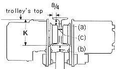
1 ) For understanding the descriptions at the upper row of the Table:
1. As for the rails belonging to the blue indicated zone, the standard type trolleys can be fitted to each of them.
2. As for the rails belonging to the gray-indicated zone, such trolleys as having special dimensions to meet them must be prepared separately.
2 ) For understanding the descriptions at the medium row of the Table:
Each of the figures indicated at this row shows the distance [ a ] ( unit:mm ) of the sketch at right side. This distance [ a ] may be zero or negative depending on the combination of the standard trolley with some types of rails: for this case, no figure is given here because such combination can't be put in actual application.
In the case of the combination indicated with a blue figure, the trolley's top is higher than the rail's top so that the trolley may touch the ceiling suspending the rail ( H less than or equal to K ) : pay attention to this.
3 ) For understanding the descriptions at the lower row of the Table:
Each of the figures indicated at this row shows the distance [ b ] ( unit:mm ) of the sketch at right side. The distance [ b ] may be zero or negative depending on the combination of the standard trolley with some type of rails: for this case, no figure is given here because such combination can't be put in actual application. Also for the rails whose thickness t2 is too thin to hold the rated load, no figure is given.
If there is even one blank at either of the upper, medium and lower rows of the Table, this means that such relevant rail can't be used to together with the trolleys.
In this way, referring to the Table, you will see what type of rail ( I beam ) is suited to the trolley you have selected.
Then it is needed to check if such rail satisfies the following condition: even if it is given a 125% of the rated safety load, its deflection amount shall be 1 / 1200 of its support span or less. That is, the I beam to be selected shall have its moment of inertia of the longitudinal section (lx ) be as follows:
lx : [ Moment of inertia of the longitudinal section ] more than or equal to [ 119.1 x W x L2 ]
In which,
W : Max. working load ( ton ) x 1.25 + Chain block's own weight ( ton )
L : Support span ( m )
For "Combination of Electric Trolleys with Traversing Rails", the following must be taken note of :
At the medium row of the table.
In the case of the combination indicated with a glay zone, the relation H less than or equal to K applies to both plain trolley and geared trolley.
In the case of the combination indicated with a blue zone, the relation H less than or equal to K applies only to the geared trolley.
*The dimensions A, B, C of the trolley will vary with the change of the traversing rail's width to be used.
The figure Y in the Table can be obtained from the following equation: Y = 1 / 2 x [ width ( mm ) of the traversing rail-Z ]